5. Using Circuit Builder
This section covers how to use the Circuit Builder to build and run Quantum Circuits in QuICScript.
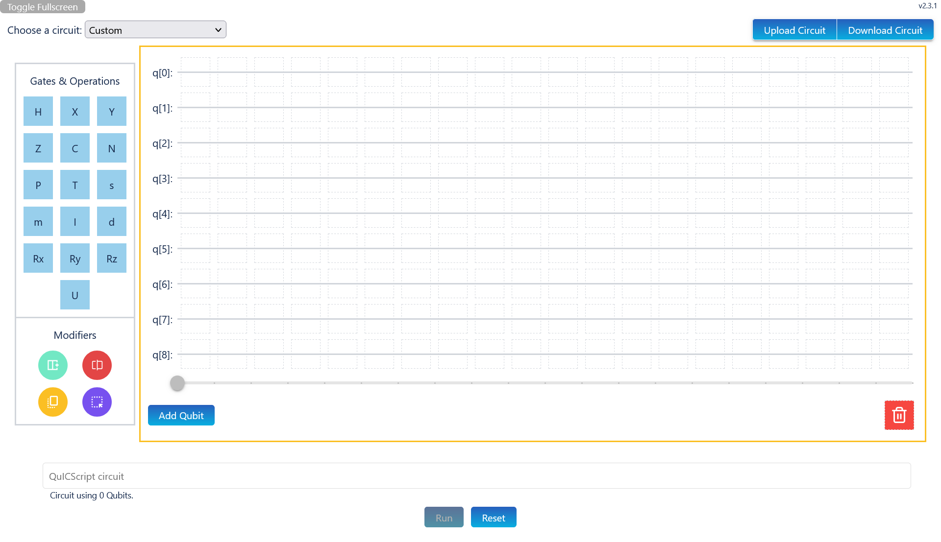
QuICScript Circuit Builder (Default Configration)
Above is what the circuit builder looks like in its entirety.
The circuit builder has different options for creating, modifying and exporting a circuit to your desired needs.
The circuit builder can be run using the Run button, and produce results that can be analysed.
The next few sections will cover how to create, modify and export a circuit. Then, the results will be covered in the following section.
5.1. Create Circuit
The Circuit Builder is feature rich with 5 different ways to create a quantum circuit:
Select a preset circuit
Drag and drop gates to form a circuit
Input a circuit using QuICScript in the input field (if enabled)
Import a QuICScript circuit file
Input a circuit using query param
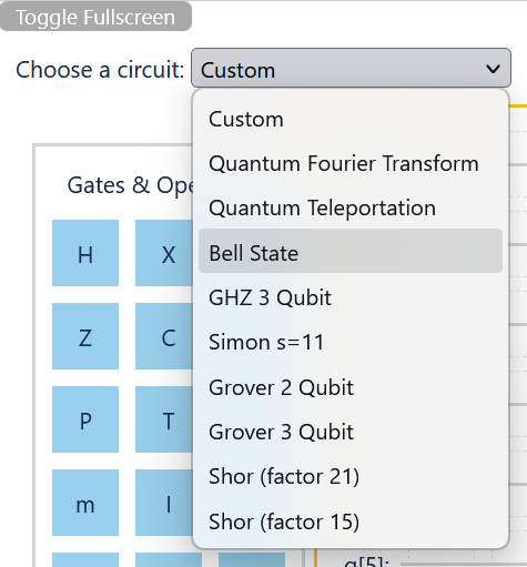
5.1.1. Select a preset circuit
There is a dropdown box on the top left of the app, that contains a series of predefined circuits.
By default the selected option will be custom as shown below:

To select a predefined circuit, click on the dropdown, then select a circuit. Below is example of what the dropdown looks like:
Then, the circuit will be rendered. You may then drag and drop gates to edit the circuit as you wish, or simply click run at the bottom to run the circuit and produce the results.
Note
To configure what predefined circuits can be shown in the dropdown, please refer to Preset Circuits configuration.
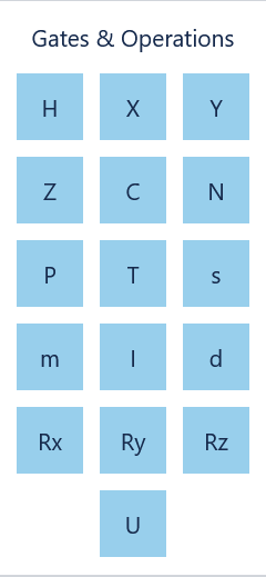
5.1.2. Drag and drop gates to form a circuit
To use drag and drop on circuit gates, simple click and hold (or tap and hold on mobile) a preferred gate in the palette on the left of the circuit builder:
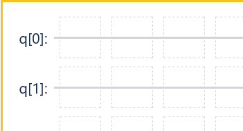
Then drag the gate to a preferred slot on the builder board, then drop it. The board has light, dotted gray lines around each slot for ease of use:
Once you have dragged your gates onto the board to form your desired circuit, simply click Run to run your quantum circuit and produce the results.
There are 3 special gates that require additional input after the gates have been dropped on the board: - U gate - Rx, Ry and Rz gates - Measurement gate
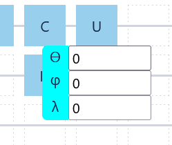
5.1.2.1. U gate input
By default, U gate will have 3 parameters tagged to it: theta, phi and lambda. These will all be zero unless changed:
You will need to manually click on each input, add values to each parameter:
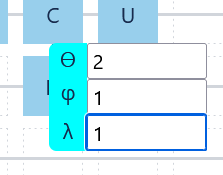
Note
Keep in mind that there are no units because the angle values are in radians, not degrees.
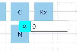
5.1.2.2. R gates Input
All 3 types of R gate have a single parameter tagged to it: alpha. Similar to U gate, this will be zero unless changed:
Similar to U gate, you will need to manually click each input to change the value of the parameter:
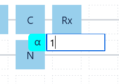
Note
Similar to U gate, all R gates dropdowns do not have units because the angle values are in radians, not degrees.
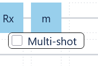
5.1.2.3. Measurement gate toggle
The measurement gate also has a dropdown with one option: Multi-shot:
When toggled (which is a global option, meaning it affects all measurement gates simultaneously), the measurement gate will change character to M:
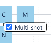
Toggling multi-shot on will prevent state from collapsing after each measurement.
5.1.3. Input a circuit using QuICScript in the input field
If enabled (see Enable Input for info), there will be circuit input field below the builder board:
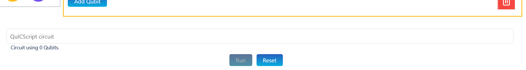
Simply fill up the input with your desired circuit and click Run:

Note
The input is in sync with the builder board, which means any changes in the input will automatically update the board and vice-versa.
5.1.4. Import a QuICScript circuit file
To import a QuICScript circuit, simply click Upload Circuit on the top left.

This will open a file dialog to select the file you would like to upload.
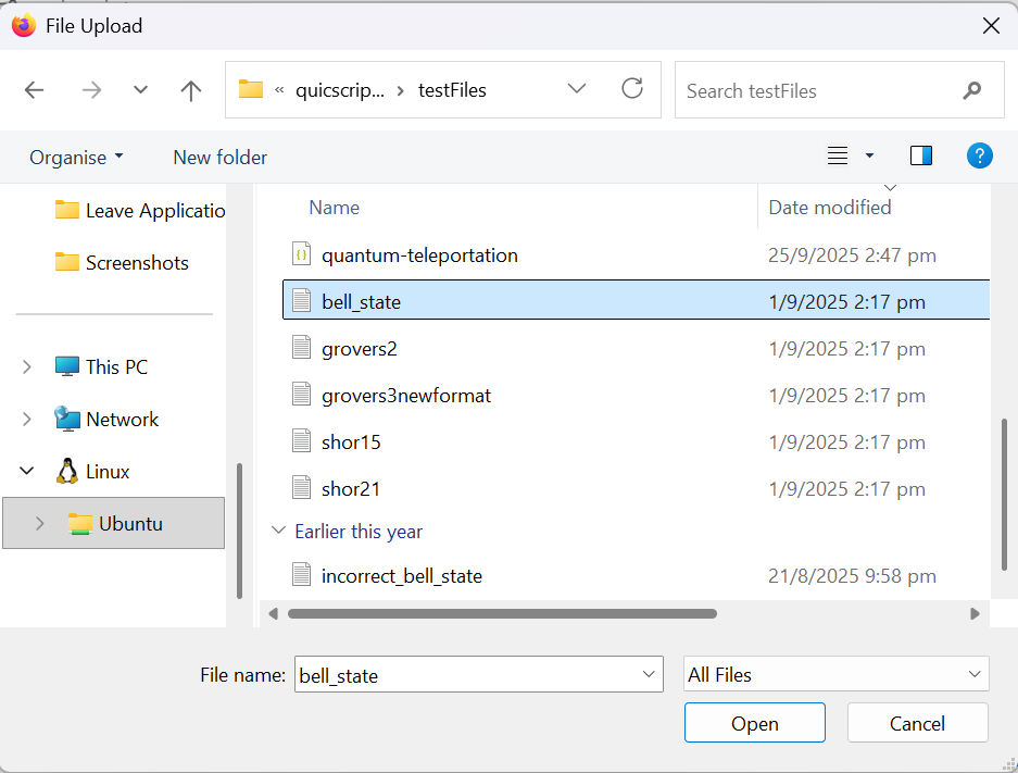
Simply select the file you wish to upload.
This will import the file, check for errors and load the circuit on the board and in the text input.
After which, just click Run to see your uploaded circuit results.
5.1.5. Input a circuit using query param
You can provide a quantum circuit using QuICScript by adding it to the URL, using the following format:
https://quicscript.pqcee.com?quicscript=[circuit]
Replace [circuit] (including the square brackets) with your desired quantum circuit. An example is shown below:
https://quicscript.pqcee.com?quicscript=HI,CN.
Then proceed to the URL. This will load the Circuit Builder with your provided circuit, and you can click Run to get your circuit results.
Attention
Do not use any other keyword other quicscript as a query param. It will render an empty circuit. (e.g. https://quicscript.pqcee.com?input=HI,CN.)
5.2. Modify Circuit
The Circuit Builder has several ways to modify both the builder board, as well as the circuit:
Add Qubit
Delete gate
Remove Qubit
Add Column
Remove Column
Copy gates
Move gates
Operations 1 to 3 (Add Qubit, Delete gate and Remove Qubit) are performed buttons and drag and drop slots in the builder board.
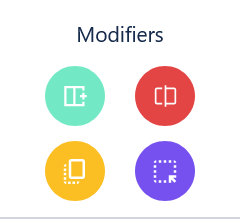
Operations 4 to 7 (Add Column, Remove Column, Copy gates and Move gates) are in the Modifier palette, and are exclusively performed using drag and drop:
5.2.1. Add Qubit
To add a new qubit row to the builder board, simply click Add Qubit on the bottom left:

This will add a new qubit row after the last qubit row.
5.2.2. Delete gate
To delete a gate, simple drag and drop the gate you would like to delete in the Dustbin gate at the bottom left of the builder board:

5.2.3. Remove Qubit
To remove a qubit row, scroll to the right and click the red x icon after the qubit row:

Note
Removing a qubit row from the circuit will also remove all gates on the qubit row from the circuit.
5.2.4. Add Column
To add a column, drag and drop the green Add column to the right modifier to the desired column:
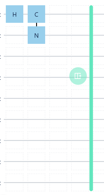
The column gap to the right of the column you hover over will be highlighted. When released, a new column will be added to the right of the dropped column.
5.2.5. Delete Column
To delete a column, drag and drop the red Delete column modifier to the desired column:
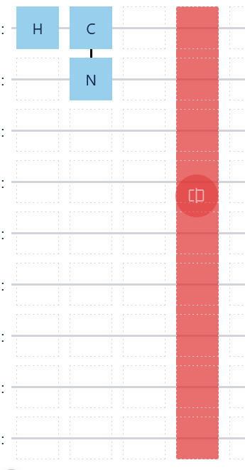
Note
Similar to Remove Qubit, when you delete a column with gates, you will also remove the gates from the circuit.
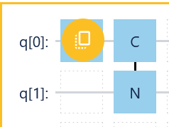
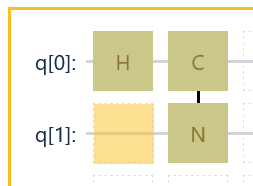
5.2.6. Copy gates
To copy a group of gates, drag and drop the yellow Copy Selector modifier at the top left of the group of gates you want to copy:
Then scroll your mouse to the bottom right of where you want the copy to end:
Note
In mobile, this second action requires you drag and drop the yellow Copy Selector modifier again on the bottom right of where you want the copy to end instead.
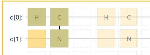
At this point, the copy selection will be highlighted yellow. Simply drag and drop the selection to your desired location to complete copy:
5.2.7. Move gates
The move modifier is very similar to the copy modifier.
To move a group of gates, drag and drop the violet Move Selector modifier at the top left of the group of gates you want to move.
Then, like copy, scroll to the bottom right (or drag and drop again to the bottom right for mobile) to select the end point for the move selection.
Similar to copy, the move selection will be highlighted, but it will be light violet.
Finally, drag and drop the selection to move the selected gates to a new location.
Note
If you would like a visual representation of what this would look like, please refer to Copy gates.
5.3. Export Circuit
To export your circuit, simple click Download Circuit on the top left of the circuit builder.
This will open a dialog prompting you to enter the filename of the text file:
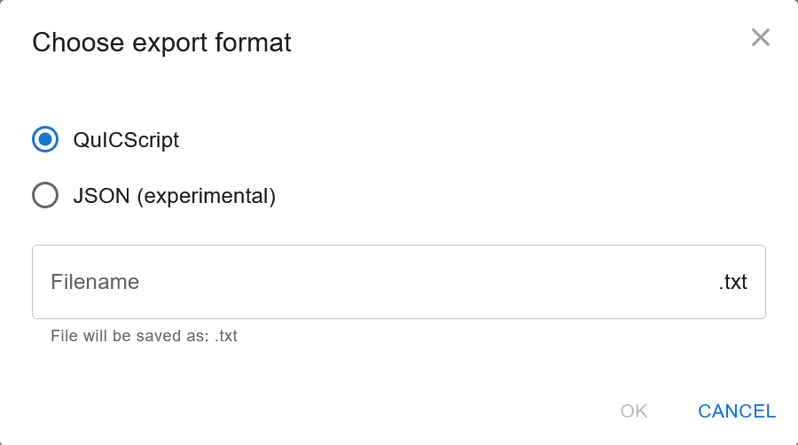
Enter a filename and click OK. Then the circuit file will be downloaded into browser downloads folder.
This file can then be used for safekeeping and for future use, by uploading this circuit file back into the circuit builder.
5.4. Circuit Results
When a circuit is built and you click Run at the bottom, a bar chart, equation and probability list is generated:
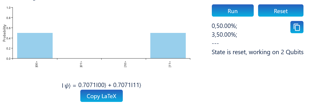
The probability list below the Run button shows a list of state probabilities. It can be copied by clicking the clipboard icon to the right of the list.
The bar chart shows the probability in bar chart form. The bar chart will only be rendered when the circuit is 4 qubits or less.
The equation provides a complex number representation of the state. It can also be copied by clicking on Copy LaTeX.
If Qibo is enabled (see Enable Qibo for more information), then you can click Qibo button to generated Qibo code to the right:
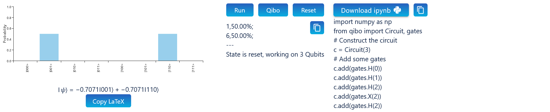
This can also be copied using the clipboard icon.
5.5. Reset Circuit
If you want to reset the circuit builder, simply click Reset. This will clear the circuit and all results.
Note
The silder results will not be cleared or change, until a new circuit is run.